
27-05-2026
Electrical Wiring Diagrams: Functions, Forms & How to Create Them
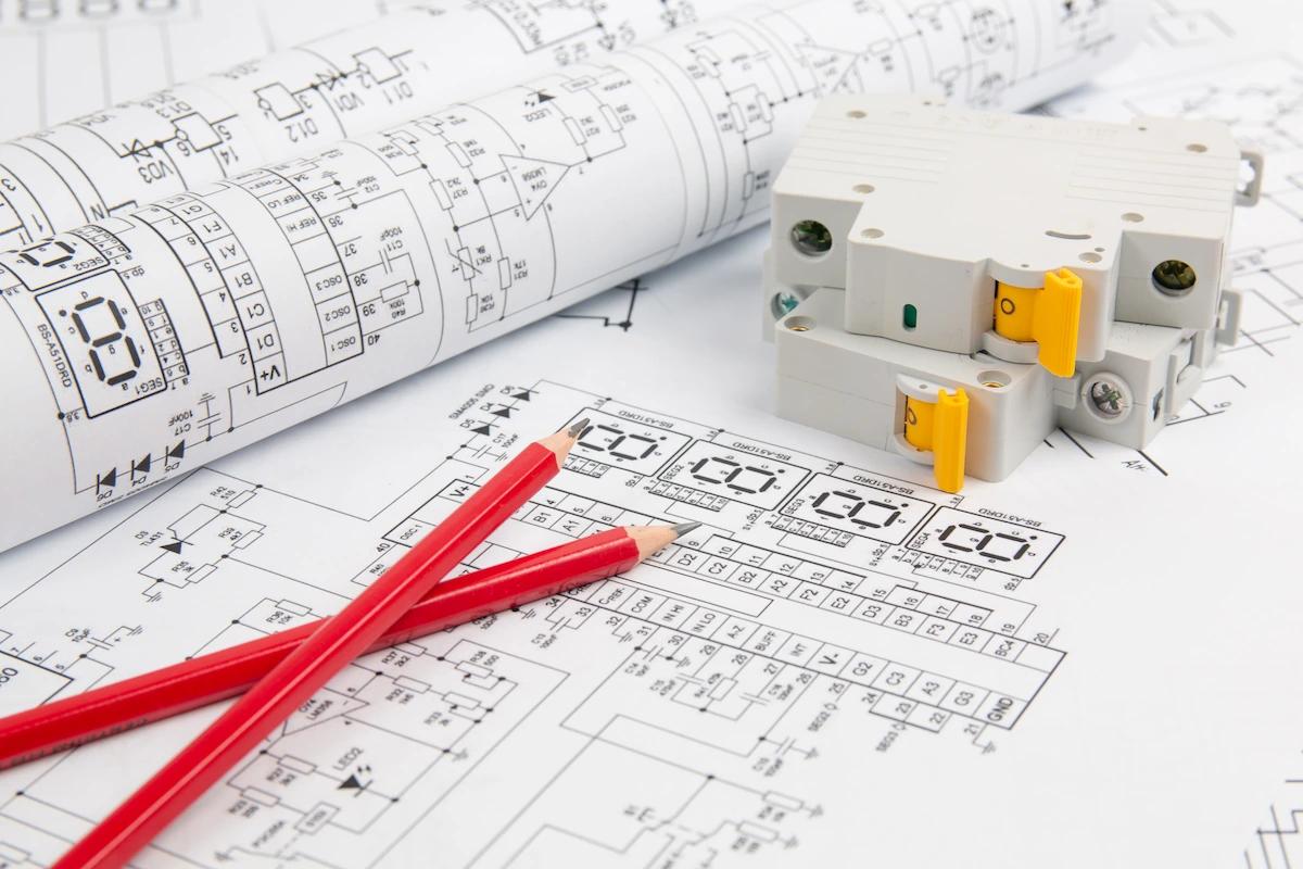
Have you ever wondered how technicians ensure that electrical energy is distributed throughout an entire building? It turns out they are using electrical wiring diagrams.
In general, an electrical wiring diagram is a visual “map” that shows how electrical components are connected to one another within a system. But why are these diagrams important? Find out the answer below.
What Is an Electrical Wiring Diagram?
An electrical wiring diagram is a schematic that illustrates how electrical components are connected within a system.
This diagram serves as a blueprint for an electrical circuit, showing how the components work together, where switches are connected, and in which direction the wires run.
In other words, an electrical wiring diagram is a “map” for technicians, electricians, or anyone trying to understand an electrical network in a building or home. This diagram can help you perform repairs and maintenance as well as plan the wiring for a building.
When discussing wiring diagrams, you might also come across the term “schematic diagram.” Both are types of electrical diagrams, but they differ in several ways.
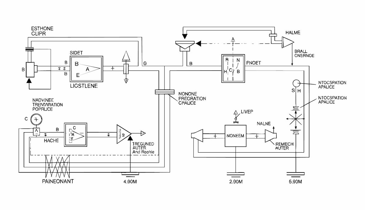
A schematic diagram is the simplest type of electrical diagram because it shows only circuit components and basic symbols on lines without indicating physical locations.
Meanwhile, a wiring diagram uses specific symbols and shows cable connections. In fact, this diagram also includes cable colors and sizes as well as physical connectors.
Schematic diagrams are typically used for troubleshooting, while wiring diagrams are used for electrical installations.
Read also: 12 Types of Power Plants for Alternative & Renewable Energy
The Functions of Electrical Wiring Diagrams
Electrical wiring diagrams offer several benefits to technicians, including:
- Installation instructions: Electrical wiring diagrams help you install new devices or electrical systems by showing where to connect the wires.
- Simplified troubleshooting: These diagrams help you quickly identify problems in electrical systems.
- Planning: These diagrams serve as blueprints, helping technicians plan electrical systems accurately.
- Safety: Electrical wiring diagrams prevent errors during electrical system installation that could lead to other problems.
- Updates: These diagrams indicate which components need to be replaced or upgraded.
Formats of Electrical Wiring Diagrams
Electrical wiring diagrams are divided into several standard formats depending on the required information. Here is the complete information:
1. Single-line Diagram (SLD)
SLDs use standard symbols and single lines to explain the parts of an electrical circuit. Single lines simplify the electrical schematic by showing only the main connections and circuit branches.
SLDs are suitable for illustrating complex electrical distribution systems, such as those in high-rise buildings or power plants.
2. Multiline Diagram
This diagram provides more detailed information, such as each conductor individually, the color, type, and size of the wires, and the connections. This diagram is ideal for the installation, maintenance, and troubleshooting of electrical systems.
Read also: Indonesia’s Renewable Energy Potential and Challenges
Components of an Electrical Wiring Diagram
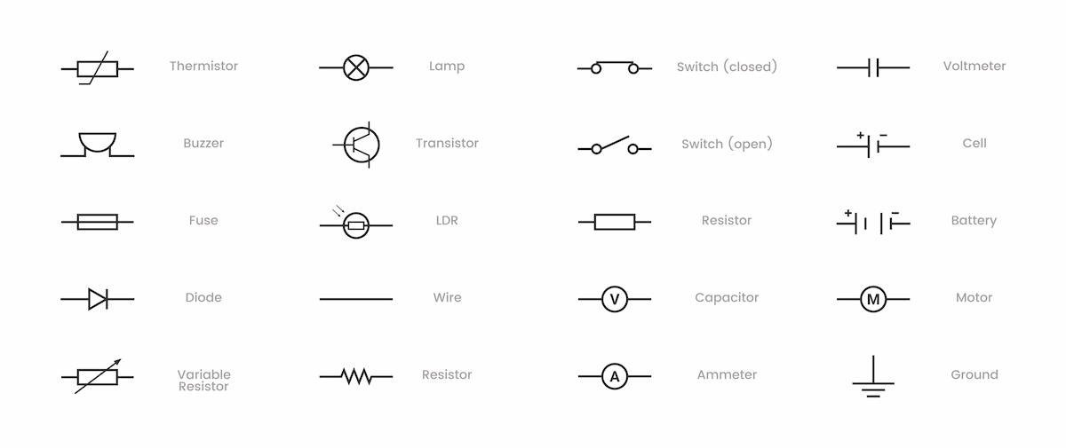
Wiring diagrams use specific symbols and labels that make it easier for technicians to interpret electrical systems. The full explanation is as follows:
1. Symbols and Labels
Symbols and labels represent different components, such as switches, conductors, capacitors, and so on. This allows you to identify the elements within the electrical wiring diagram. Meanwhile, labels provide additional details to understand the role of each component.
Generally, the following symbols appear on electrical wiring diagrams:
- Power source: The symbol is a circle with a “+” or “-” indicating the positive or negative terminal.
- Resistor: Represented by a zigzag line. A resistor controls the flow of electricity by adding resistance to the circuit.
- Capacitor: Represented by two parallel lines (one of which may be curved). A capacitor indicates that electrical energy is temporarily stored.
- Transformer (trafo): Represented by adjacent coils or a rectangle with lines on both sides, which represent its role in changing voltage.
- Motor: Represented by the letter “M” or a circle with an “X” inside it. A motor converts electrical energy into mechanical energy.
- Inductor: Used in transformers or motors. Represented by several curved lines or a rectangle.
- Switch: Controls the flow of electric current. Represented as a closed or open “T.”
- Fuse: Represented by a simple line with a rectangle in the center.
- Circuit breaker: Represented by two small circles with a line in the center. Fuses and circuit breakers serve to protect circuits from overloads.
- Connection: Connection symbols are typically small dots at the intersection of two lines, indicating that wires are connected. If you see intersecting lines without a dot, it means the wires are not connected.
2. Organization and Layout
A well-designed electrical wiring diagram has an easy structure to follow and logically shows the location of components. Organization and layout help you track the flow from start to finish, facilitate troubleshooting, and provide a clear picture of the circuit design.
3. Lines and Connections
The lines on an electrical wiring diagram connect the components of the electrical system. Dashed lines indicate alternative paths, while solid lines represent direct connections.
How to Create an Electrical Wiring Diagram
To create an electrical wiring diagram, you can follow these steps:
- Planning the circuit layout: Map out where you will place the components and how they connect to form a larger system.
- Choosing design tools: You can use Microsoft Visio to create simple diagrams. However, if the electrical circuit is quite complex, you can use AutoCAD Electrical.
- Drawing the diagram: Start by positioning the main components according to the circuit layout plan. Next, draw lines representing the wires (use different colors to distinguish one connection from another). Then, use the appropriate symbols and labels. Finally, review the diagram and make corrections if any connections seem illogical.
Electrical System Services from Chandra Asri Group
Electrical system installation can be complex for some people, especially when intended for office buildings. If your company needs a reliable electrical system, Chandra Asri Group, as #YourGrowthPartner, offers trusted energy solutions.
Through our subsidiary, PT Krakatau Chandra Energi (KCE), we provide services in the fields of power supply, electrical services, and renewable energy.
KCE’s core business focuses on electricity supply supported by power plants with a total capacity of 120 MW. Currently, KCE serves over 200 customers from the industrial, commercial, social, and government sectors, as well as more than 1,000 residential customers.
In its operations, KCE utilizes combined-cycle gas turbine (CCGT) technology and ensures that the electricity it generates meets industry-standard quality requirements.
Additionally, we provide power services, including operations and maintenance (O&M), engineering, procurement, and construction (EPC), as well as repair services, such as overhauls of transformers and electric motors.
Furthermore, we offer solar panel solutions available in four types of systems that can be tailored to specific needs, namely:
- On-grid solar system: A system that connects solar panels to the public power grid, allowing the generated energy to be directly fed into the grid without a backup battery.
- Off-grid solar system: A solar panel system that operates independently without being connected to the power grid, utilizing a battery for energy storage.
- Solar on-grid with battery backup system: A system that combines solar panels with a battery as a backup power source in the event of a power outage from the main grid.
- Solar hybrid system: A system that integrates solar panels with other energy sources to generate a more stable and sustainable power supply.
Do not hesitate to entrust your company’s electricity needs to us! Contact us now for a consultation and to get the best quote!
Read also: Why Should We Save Energy? 4 Reasons You Must Know
.png&w=3840&q=75)